MSP430 Expansion Board Design
This site provides information about the design of an expansion board, specifically for the MSP430-449STK2 development board. The expansion board provides: Regulated power, 4 LED’s, a single SPI Digital to Analog Converter (DAC), an SPI temperature sensor, a pressure sensor, and a keypad interface.
MSP430-449STK2 Development Board
|
Figure 1: MSP430-449STK2 |
DOCUMENTS: HARDWARE:
SOFTWARE:
|
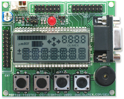
The MSP430-449STK2 MSP430F449 STARTERKIT DEVELOPMENT BOARD from Olimex is shown above in Figure 1. Visit the Texas Instruments website for more information on the MSP430F449. Some links that give more information, and support for this family of Microcontrollers are provided below.
MSP430x4xx - Flash/ROM LCD
- Technical Documents
- Application Notes (From TI)
- Code Examples (Click here for more examples from TI)
- Compilers/Assemblers/Linkers
- IAR Embedded Workbench Kickstart - Free 4KB IDE (Click here for more info from TI)
- TI Code Composer Essentials Evaluation - Free 8KB IDE (Click here for more info from TI)
MSP430-449STK2 Expansion Board
|
Figure 2: MSP430-449STK2 Expansion Board |
SOFTWARE: HARDWARE: |
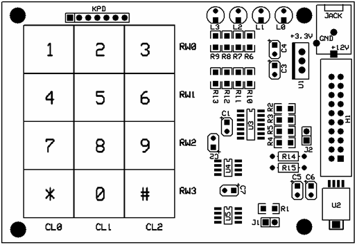
The MSP430-449STK2 Expansion Board shown in Figure
2 interfaces the different components listed below, in Table 1, to
the development board through header H1.
|
Part |
Datasheet |
|
12-Bit DAC with SPI Interface |
|
|
Thermal Sensor with SPI Interface |
|
|
Single Supply Quad Opamp |
|
|
3x4 Rear |
|
|
0 to 50kPa Ported Gauge Pressure Sensor |
|
|
3.3V Regulator |
|
|
Table 1: Component Datasheets |
|
System Design
|
DAC |
|
|
Thermal Sensor |
|
|
3x4 Keypad |
|
|
Pressure Sensor |
|
|
LED Configuration |
|
|
Table 2: System Design for each Component |
|
Software
Various code examples for use of different components are provided in Table 3. These examples were tested using IAR Embedded Workbench IDE so be sure to use this code in the IAR environment. A zip file with all the following software is provided here.
Table 2: Code Examples
|
Component |
Code Example |
|
Buzzer |
buzzer.c |
|
3x4 Keypad |
keypad.c |
|
LED Configuration |
LED.c |
|
Microchip DAC |
mcpdac.c |
|
Microchip Temperature Sensor |
temp.c |
|
Timer B |
timerb.c |
|
Pressure Sensor |
pressure.c |
The test program provided in Table 3 tests all the different components shown in Table 2. The exception is that the test program performs a complete test of the expansion board and MSP430-449STK2 to ensure that each component is working properly.
Table 3: Test Program
|
Test
Program |
|
testprgm.c |